
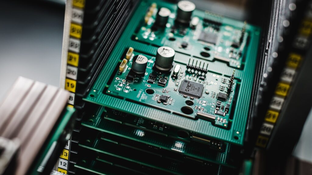
Image / Sellectronics
From secure communications and defence systems to aerospace, automotive and industrial applications, electronic assemblies need to deliver consistent performance throughout their service life.
High-reliability products require more than a correctly manufactured PCB assembly: a combination of inspection and testing methods can identify different types of defects, helping manufacturers verify the quality and performance of an assembly at multiple stages.
Why standard testing is not enough
As functionality increases, so does the potential for manufacturing and electrical faults. While a defective PCB in a commercial product may result in inconvenience or warranty costs, failures within emergency communications, aerospace controls or military electronics can affect safety and operational capability.
A defect discovered during PCB assembly is generally easier and less expensive to address than one found after final integration or once a product has entered service.
PCB inspection: the first layer of quality assurance
PCB inspection provides the earliest opportunity to identify manufacturing defects before electrical testing begins, focusing primarily on physical characteristics of the assembly to help detect issues that may later develop into failures.
Automated Optical Inspection (AOI) is one of the most widely used technologies in modern electronics assembly. AOI systems use high-resolution cameras and image processing algorithms to compare assembled boards against reference data. They can identify missing components, incorrect placement, polarity errors, solder bridging, insufficient solder, tombstoning and other assembly defects with remarkable consistency and speed.
For boards featuring fine-pitch components, BGAs, QFNs and high-density interconnects, visual inspection has limitations. X-ray inspection can examine areas that cannot be seen optically, including hidden solder joints and internal board structures. Using AOI alongside X-ray inspection therefore provides broader physical coverage across the assembled board, including concealed solder joints and internal structures.
PCB testing: verifying electrical integrity
While inspection identifies physical defects, PCB testing verifies that the assembled board’s electrical connections and circuitry perform as intended.
In-Circuit Testing (ICT) remains one of the most effective methods for detecting manufacturing-related electrical faults. Using a bed-of-nails fixture, ICT probes numerous test points across the board and measures parameters such as continuity, resistance, capacitance, diode behaviour and component values. It can identify open circuits, short circuits, incorrect component values, missing devices and solder-related defects that may not be visible during inspection.
Modern PCB designs frequently contain components with limited physical access, making traditional ICT increasingly challenging. High-density layouts, fine pitch packages and extensive use of surface-mount technology can restrict access to test points and reduce achievable test coverage.
Boundary scan: testing without physical access
Boundary scan is another way to assess electrical connectivity where conventional physical access is restricted.
Based on the IEEE 1149.1 JTAG standard, boundary scan uses test functionality built into compatible integrated circuits. Signals can be driven and observed through dedicated JTAG interfaces, allowing manufacturers to assess connections between devices without needing direct access to every node.It can help identify opens, shorts and solder faults, as well as support device programming, firmware loading and digital system debugging.
PCB functional testing
PCB functional testing evaluates the assembly under operating conditions that closely resemble real-world use. It verifies that the board powers up correctly, firmware executes as expected, communication interfaces operate properly and system-level behaviour meets design requirements.
Depending on the application, this may include testing analogue and digital I/O, radio frequency performance, sensor interfaces, power management systems, battery charging circuits, display functions and human-machine interfaces.
In mission-critical products, functional testing provides an important opportunity to identify latent or intermittent faults before deployment. End-of-line testing may include automated functional sequences, communication verification and performance validation across multiple operating modes.
Why are multiple testing methods necessary?
No single testing technique can identify every possible issue within a complex electronic assembly. Combining inspection, electrical and functional testing provides different levels of assurance, from physical assembly quality through to operational performance.
The most appropriate combination depends on factors such as board complexity, component technology, accessibility, application and the consequences of failure.
Designing for testability from the beginning
One of the most important principles in high-reliability manufacturing is that testing should be considered during product design. Design for Manufacturing (DFM) ensures the PCB can be manufactured consistently and economically, while Design for Test (DFT) ensures adequate test access is incorporated into the design from the outset.
DFT considerations may include test point placement, JTAG accessibility, partitioning of functional blocks, power sequencing support and provision for automated test fixtures. Early collaboration between design engineers and manufacturing teams can dramatically improve achievable test coverage and reduce production risk.
As an experienced electronics manufacturer, UK-based, we can provide valuable input during these early design stages, helping optimise both manufacturability and testability before production begins.
Traceability and test coverage
Mission-critical industries increasingly require comprehensive traceability throughout the manufacturing process. Test coverage data, component lot information, inspection records, programming history and process parameters must often be retained for regulatory compliance, quality audits and long-term product support.
Traceability enables rapid root-cause analysis if field failures occur and supports continuous improvement across future production runs. It also provides evidence that manufacturing processes remain controlled and repeatable.
Sellectronics integrates inspection, testing and manufacturing data into structured quality systems, helping customers maintain the documentation and evidence required for demanding applications.
Environmental testing for demanding applications
Aerospace, defence, automotive and industrial applications may expose assemblies to extreme temperatures, vibration, shock, humidity, electromagnetic interference and prolonged operational duty cycles.
Environmental testing helps identify weaknesses that may not appear during standard functional testing. Thermal cycling can reveal solder fatigue and material expansion issues. Vibration testing identifies mechanical weaknesses and connector reliability problems. Humidity and environmental stress testing expose sealing, contamination and corrosion related vulnerabilities.
These tests help demonstrate how an assembly is likely to perform beyond controlled factory conditions, providing additional assurance before deployment.
Building reliability through testing
Effective testing is about applying the right methods at the right stages of production. The most appropriate approach will depend on the board’s design, application, component technology and potential failure risks.
From PCB inspection and electrical testing through to functional and environmental assessment, a structured testing strategy helps manufacturers identify issues early and maintain confidence in product quality.